

 – how to use the display module")
A complete device consists of functional blocks, many of which can be used multiple times. For example, if you build a frequency counter with a micro
A complete device consists of functional blocks, many of which can be used multiple times. For example, if you build a frequency counter with a microcontroller, you will need to use the same components as is in the case of building a time relay, plus the amplifier unit. The system described here can be understood as a microcontroller with its surrounding units (resistors, capacitators, quartz and other), display, buttons, and terminals/connectors. Of course, the frequency counter will not require a transmitter that switches on an external device, and the time relay will not need a broadband amplifier, but the core remains the same. Therefore, the key to making apps on your own is to understand the principles of operation of each of the functional blocks, and then to combine their functionalities.
Such platforms as Arduino do not require any background knowledge on the operation of every single component from the user. You can simply connect the base board with a module/extension and make a full functional, up and running app. On the other hand, if you do not have any basic knowledge of the components, then in the case of problems you will probably struggle looking for the solution on your own. The truth is that when using Arduino components, you usually expect an instant effect. It is hard to reconcile such expectations with a need to acquire specific knowledge, because you just need to enter a few commands to see the first effects on the display, but understanding the whole process takes more time.
Having in mind the differences mentioned above, each of the articles in this cycle is going to be divided into two parts. The first one is going to describe how to reach the goal discussed in the article. The second one is focused on the principles of functioning of a given unit or solution.
We will start with the LCD module, because thanks to it you can see the effect of your work really soon. Then, the other elements of the user interface and the selected external systems (sensors and executive elements) will be discussed. In the meantime, you will get familiar with some useful tricks and programming methods. This is all possible thanks to the Arduino platform, which is budget-friendly, easily available and will let you use your new knowledge to build complete devices and their prototypes.
The character LCD module
The basic interface between the microcontroller and the user is usually composed of a display and a button or a set of buttons. The display is used to inform the user about microcontroller activity, whereas the buttons – sometimes replaced with pulse generator – can be used to enter a command or data. The range of available products includes various kinds of displays (including displays equipped with a touch panel), among which character LCDs with a HD44780 controller have become an informal standard much appreciated by the users.
In the first example, an Arduino UNO R3 board, a breadboard, a character LCD module with two 16-character lines (verses) in each of them, and a few connection cables are going to be used. Of course, it is just a suggestion – the display can be connected in any way you want, for example by way of soldering it to the board. Here, we propose a method which gives you the widest possibility to modify and change the system of connections.
If the display module features goldpins, just stick it into the breadboard. Then, connect the display with Arduino UNO board, as described in Table 1.
Table 1. Connections of a character LCD with an Arduino UNO board
| No. of the display terminal | Name of the display signal | Name of the Arduino connector | Name of the Arduino signal |
| 1 | VSS | Power | GND |
| 2 | VDD | Power | +5V |
| 3 | V0 | Power | GND |
| 4 | RS | Analog In | A4 (PC4) |
| 5 | R/W | Power | GND |
| 6 | E | Analog In | A5 (PC5) |
| 7 | DB0 | – | – |
| 8 | DB1 | – | – |
| 9 | DB2 | – | – |
| 10 | DB3 | – | – |
| 11 | DB4 | Analog In | A0 (PC0) |
| 12 | DB5 | Analog In | A1 (PC1) |
| 13 | DB6 | Analog In | A2 (PC2) |
| 14 | DB7 | Analog In | A3 |
| 15 (optional) | LED+ | Power | 3.3V |
| 16 (optional) | LED- | Power | GND |
You need to remember that if you have GND connected from the Power connector to the breadboard, you can make connections within the breadboard without the need to make a connection to the Power connector every time.
You have to use the Power connector, because it will supply power to the display. The Analog In connector is located right next to the Power connector, so the microcontroller terminals available there are used as the most convenient ones. However, do not get misled by the name – in order to manipulate the display module, digital outputs are required, not analogue inputs/outputs. The connector is called Analog In, as optional analogue inputs are available here, which still can be set up to operate in different modes, including as digital outputs. The A0 analogue input is PC0 port, A1 – PC1, and so on (see also: terminals of the ATmega328PU microcontroller).
From among many programmable controllers available for Arduino, a LiquidCrystal library was selected to control the LCD operation. After making a draft, we will add the library in the first line of the program, using the command: #include. With the display already connected to microcontroller according to the instructions above, you can make the first draft controlling the LCD module.
Connect the Arduino board to your computer via the USB port. Choose File and then New (Ctrl+N) from the Arduino menu. You will see a window similar to the one in Figure1. The key word “void” informs you that a function will be created here that does not return any value. The word “void” is followed by the name of the function, and the opening and closing brace brackets, “{” and “}”, inform us about its beginning and end.
When you make a new draft, the Arduino environment informs you about the need to define two special functions: one is void setup(), which describes the configuration of the microcontroller and comprises instructions performed once at the beginning of the program operation, and the other one is void loop(), with operations performed in an infinite loop.
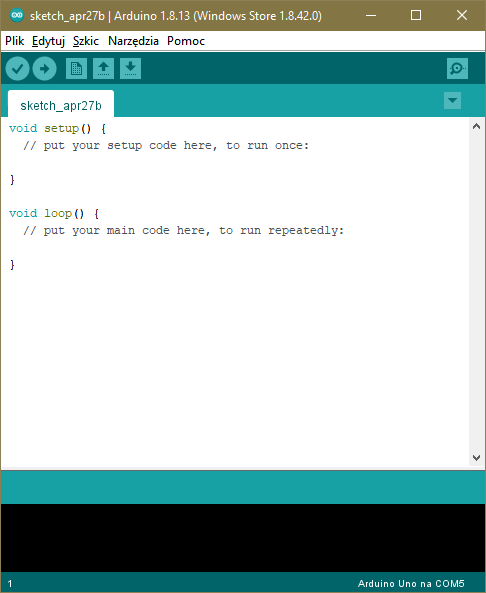
Figure 1. Window of a new draft for Arduino
Why the application program must be launched in an infinite loop? Windows or Linux apps run under the control of the operating system. If you launch a Windows app, after work it returns to where it was called, most often to the desktop, command line etc. From this moment on, the processor is controlled by the operating system. The microcontroller on the Arduino UNO board does not have any operating system uploaded, so it is the programmer that needs to make sure that the app terminates safely. You can do this by switching off the microcontroller (for example by entering the sleep mode) or by looping the command execution in order to prevent instructions from outside the required memory range from being executed. You can do it by using the void loop() function or in a different way, as will be discussed later.
Before information can be shown on the display, you need to configure the microcontroller. In this example, you just need to configure the outputs which control the display.
At the beginning of your draft, add the library of display functions.
#include <LiquidCrystal.h>
Next, to make it all more convenient and clear, define the names of terminals from microcontroller’s port C using the #define directive.
//port PC
#define pc0 A0
#define pc1 A1
#define pc2 A2
#define pc3 A3
#define pc4 A4
#define pc5 A5
Now, we need to inform the microcontroller which terminals the display is connected to. In order to do it, we use the lcd() function, in which the list of arguments instructs the processor where the signals are fed. When changing the terminals, you need to stick to an appropriate sequence: :LiquidCrystal lcd(RS, Enable, D4, D5, D6, D7). When creating the list of arguments, use Table 1, which contains a list of connections between Arduino and the LCD module: LiquidCrystal lcd(pc4, pc5, pc0, pc1, pc2, pc3).
Now, it is time to move on to the configuration of the output operation mode – you need to set these as digital outputs inside the
void setup function():
pinMode(pc0, OUTPUT);
pinMode(pc1, OUTPUT);
pinMode(pc2, OUTPUT);
pinMode(pc3, OUTPUT);
pinMode(pc4, OUTPUT);
pinMode(pc5, OUTPUT);
Next, we initialize the display by setting the number of columns, rows and (in the first step) by deleting everything from the screen. After the initialization, the LCD screen should be clear, but for the sake of safety and to get things started correctly, it’s good to do one more thing:
lcd.begin(16, 2);
lcd.clear();
After that, it only takes one command to display the message:
Icd print(“Hello!);
Do not insert any commands in the loop() function, otherwise the program will simply “freeze” in the infinite loop, wasting the CPU time. Admittedly, you could turn on the power saving mode, because the message on the screen wouldn’t change anyway, but this would require further hardware exploration, which is not advisable at this point.
You can find the whole program displaying the “Hello” message in the additional material attached to this text. If the description above and the achieved effect is satisfactory, you can skip reading the remaining part of the text. In the next article, we will deal some more advanced operations with displayed messages.
LCD module operation
Thorough analysis of this subject should in fact start with the description of the microcontroller that is mounted on the Arduino PCB. However, it is a very wide topic, so we will focus on how the LCD module works in the first place.
Some basic knowledge of memory and digital circuits in general is required to understand how to operate the LCD control module. It is essential to know concepts such as high and low digital logic levels, waveform, data, 8-bit number, byte, bit, falling and rising edge. This is necessary, because the operating system sees the module as a kind of digital memory with which the microcontroller can communicate bidirectionally. The LCD module has its own microcontroller (the HD44780 mentioned at the beginning or similar), which not only receives the data to be displayed, but also executes the commands related to the operation of the LCD module and operates the display. The microcontroller embedded in the display module has a strictly specialized, autonomous function, so often such systems are called slave systems. On the other hand, the microcontroller built into the Arduino board performs the control and superior function – usually such systems are referred to as master systems. You will come across these terms many times in descriptions of various devices attached to the microcontroller.
Logical “0” and “1”
Let’s go back to the basics for a little while. In CMOS circuits (this is the technology in which most of today’s ICs are made), a logical “1” means at least 95% of the system supply voltage, while a logical “0” is the voltage equal to or less than 0.3 V. If the CPU circuit has a built-in power supply, which is often the case for complex processors, a logical “1” is defined in reference to the internal power source. However, if a CMOS chip has inputs that are compliant with TTL levels, then a logical “1” is a voltage higher than 2.4 V. Therefore, when in doubt, look at the data sheet of a given circuit. You can easily find it on the Internet.
Rising and falling edge
A change in the logic level entails a voltage change. This change occurs by leaps and bounds, but still, over some time. When the level changes from “0” to “1”, it’s a rising edge, and when it changes from “1” to “0”, it is a falling edge. The duration of the transition is then called the rising or falling time, respectively. It is usually a few nanoseconds, but this is not the rule.
In a microcontroller, a single line carrying the “0” or “1” level is called a data bit. 8 such lines form a byte. An AVR microcontroller, such as the one built into the Arduino UNO, has an 8-bit data word, so it can process 1-byte words, in decimal, in the 0…255 range. If the number is greater than 255, it needs to be divided into “portions” and it requires operations to be performed on them, and then the result to be assembled. However, we don’t have to worry about that, because it is done in the background by the Arduino language compiler. Still, we need to be aware that the more bits a variable requires to be stored, the longer it will be processed by the microcontroller.
Controlling the LCD module
In this example, the master microcontroller controls the LCD display module with its output signals. It controls the logic levels on the inputs of the display mode by changing its own output signals. In this way, it can select the moment of data recording and the memory area in which the data will be saved:
- Logical “1” at the RS (Register Select) input causes data recording in the video memory, while logical “0” causes data recording in the control register of the LCD module. The master microcontroller must be able to control this input to properly send commands for the display controller (RS=0) and to send the data to be displayed (RS=1). Setting this input as a constant and high logic level will prevent the LCD module from executing “clear the display” commands and from the correct initialization (control register will be unavailable).
- Logical “1” at the R/W (Read/Write) input causes the data reading, and the logical “0” – recording. In our example, we forced the permanently low level on this LCD module input, by connecting it to GND. This is correct only if you save data on the display and you don’t read it. By connecting this input to a constant logic level, you will lose the ability to read the display memory and its control register, and thus the “busy” signal. Testing the “busy” signal speeds up the operation of the display module and allows you to test its controller’s response to received data, but it also takes up an extra line of the master microcontroller ports, requires routing one more connection, and complicates the operating program a bit.
- The falling edge at the “E” (Enable) input will copy the logic levels (containing 4- or 8-bit data words) from DB0…DB7 inputs to the internal memory of the LCD module.
There are two operating modes available for operating the LCD character module, namely the 8- bit and 4-bit modes. In the first one, connecting the display requires at least 10 data lines (RS, E, D0…D7). This mode is very efficient if you can attach to the master system the display as a memory on the 8-bit data bus. Addressing the display module sets the high level at the Enable input, low or high level (depending on whether it is a command or data to be displayed) at RS, sets the data at the bus, and changes the level at Enable to low. In some systems, this simplifies the operating program in a significant way.
In the 4-bit mode, we still use an 8-bit word, but only inputs D4…D7 of the LCD module are connected to the master system, with the 8-bit data words being divided into two portions of 4 bits each. This complicates the operating program and does not allow to easily connect the display module to the master system, but saves 4 GPIO lines of the microcontroller.
In simplified LCD module operation programs that don’t use the R/W line, it is assumed a priori that the display module is working correctly. Some default time is set, such as the execution of the longest running command (typically about 2 milliseconds), and it is assumed that after that time the display has executed the command or is displaying the character, and you can send more data. Usually, the microcontroller built into the display module is faster – only the clear command takes 2 milliseconds to execute. On the other hand, if – as in this example – you have 2 lines of 8 characters on the screen, it doesn’t matter whether you send 16 bytes in 32 milliseconds or 100 microseconds. No user will be able to notice the difference anyway. It is only an issue, when we work with graphic displays, to which much more data is transmitted.
Arduino doesn’t give us a lot of freedom when controlling the display. The ATmega328 microcontroller built into the Arduino UNO doesn’t have external address lines, so controlling the display in the 8-bit mode with addressing in the same way as in the case of an external memory is out of the question. However, if we use one more GPIO port to control the R/W signal, we can test the busy flag and read the contents of registers and memory of the LCD module.
To configure the way in which the display is attached to the LiquidCrystal.h library, the function of the same name is used, i.e. LiquidCrystal (). The manner in which the display is attached is determined by the list of arguments of the function call:
- LiquidCrystal(rs, enable, d4, d5, d6, d7) – 4-bit interface, with no R/W input control of the display module and no data readability.
- LiquidCrystal(rs, rw, enable, d4, d5, d6, d7) – 4-bit interface, with control of R/W input of LCD module and with possibility to read data from the display.
- LiquidCrystal(rs, enable, d0, d1, d2, d3, d4, d5, d6, d7) – 8-bit interface, but without the ability to read data.
- LiquidCrystal(rs, rw, enable, d0, d1, d2, d3, d4, d5, d6, d7) – 8-bit interface, with data readability.
The HD44780 controller is a universal circuit, adapted for LCD screens with different numbers of characters (columns and rows). As a result, after powering on, the controller doesn’t detect which screen is attached and it needs to be configured for a proper use. In Arduino, this is done by the begin() function, whose arguments are the number of columns and the number of rows. For example, if you have a display with 2 lines of 16 characters each, call begin(16, 2).
In our example program, the clear() function is used to clean the screen. It is good practice to use this function first, after initializing the LCD module, because there are some displays that show random characters after initialization. We have also used the print() function. The arguments of its call are the data to be displayed, for example a number or a text and – in the case of numbers – the base, which for decimal numbers is equal to “DEC”, binary “BIN”, hexadecimal “HEX”, octal “OCT”. The print() function converts numbers for us, if we need to show them in different number systems:
- print(10) or print(10, DEC) -> displays 10,
- print(10, BIN) -> displays 1010,
- print(10, HEX) -> displays A,
- print(10, OCT) -> displays 12.
- print(“Hello!”) -> displays Hello!
Print places the displayed characters starting from the current cursor position. Typically, after the clear() command, the cursor is in the upper left corner of the LCD screen.
The LiquidCrystal.h library function contains many other useful functions, but we will discuss them in the next article. You have already learnt a lot – it’s time to have some rest.
Text prepared by Transfer Multisort Elektronik Sp. z o.o.
The original source of text: tme.euRELATED ITEMS:ARDUINO, FEATURED, LATEST ELECTRONICS NEWS
COMMENTS